SailNet Community banner
  • SailNet is a forum community dedicated to Sailing enthusiasts. Come join the discussion about sailing, modifications, classifieds, troubleshooting, repairs, reviews, maintenance, and more!

Updating DC System

18K views 29 replies 11 participants last post by  Boomer  
#1 ·
I'm updating my batteries and battery cabling on my boat. I'm planning on replacing the two 8Ds I have, with six group 24 or 27 AGMs. Five are for the house and one as a reserve/start battery. I'm going to be moving the house bank to under the settee, and put the reserve/start in the engine room. I'm also going to replace all the battery cables and add terminal blocks, a battery monitor and a controller for future solar panels. My alternator is a delco 55amp. I might be upgrading it to 80 or 120 Amp, maybe?(not sure if I need to). Engine is a Perkins 4108. The battery charger is a Xantrex truecharge2 40A. The battery switch is a 1,2,both switch. Here is a diagram of what I think I want to do. Am I heading in the right direction?

Photobucket
 
#2 · (Edited)
That's great, well done. The wiring layout and the use of the 1-2-B switch is well understood. Only suggestion: have you considered golf cart batteries instead of the five Grp 24 or 27? With four golf carts you'd get the same or maybe more ah in a smaller footprint if you have the height.

Again, well done, many of us wish more "I'm getting started on new wiring" questions came this well prepared! :)
 
#4 · (Edited)
Stu beat me to it - I suggest golf carts as well. With 5 group 24 AGM's you are at about 400 AH, with group 27 about 500 AH. 4 good golf cart batteries is about 480 AH and they have much thicker plates and more durability than any 12 volt battery.

And I wonder if AGM batteries are the best choice, whatever group you decide on. With AGM's, even if you don't upgrade the alt, an external regulator with both alt and battery temp sensors is really a must. Balmar MC-612 is a good choice. The reason is that an AGM bank, if down 40 or 50%, will call on your alt to run at max output for more time than it is designed to handle.

The schematic looks good.

Lifeline makes 6 volt AGM's in 220, 300, and 400 AH sizes. http://www.lifelinebatteries.com/marinedeepcycle.php
 
#7 ·
You might want to consider a fuse before the bus bar from the alternator if there's any distance between the bus bar and the battery bank. We have also been suggesting the use of a switch in that wire to be easily able to turn off the power to the alternator if you're working on it. I don't have a switch, I just remove the fuse.

Also fuse your solar input, don't know what you have in your controller.
 
#8 ·
Move the starter wire over to SW2, upgrade the wiring on the start battery to 2/0, fuse the solar, alternator, and charger wires, and you're done. The plan would be to leave the battery switch on Bat 1 and start the engine with Bat 2, unless it fails--then you would turn the battery switch to Both.
 
#9 · (Edited)
Don,

It is a 1/2/BOTH/OFF.... Most folks with 1/2/BOTH/OFF switches simply leave it on the HOUSE and do everything in that battery position, and keep the #2 as a reserve.

CTJ1950,

The diagram looks great just add some fuses and you're good to go. My only concern is a 55A alt on AGM's.. I have seen far to many cook themselves when asked to charge large banks of wets and smaller banks of AGM. If you can get an alt shop to convert it to external regulation, and then you add an alt temp sensor, you'll be okay with AGM. Keep in mind that both AGM and Gel cells can still vent if over charged and the ABYC makes not "exceptions" on battery venting requirements of wets, gels or AGM.. If charging wet cells properly this is pretty much a non-issue and the vast majority of boats in the world have wet cells, most of which are in cabin spaces...

As Don said your #2 bank should also be the same battery wire gauge as the other bank. 2/0 is generally a good size...

The ACR should ideally also be fused if those wires could cause an issue. Blue Sea also recommends a 15A fuse in the neg wire of the ACR on top of fusing the pos leads..

Technically you'd be covered by the bank fuses if you changed the ACR wires to 2/0. 2GA can not be protected be a 250A fuse. The max ampacity rating for 2Ga outside an engine space is 210A. You can also go larger on those fuses as 2/0 can be 330A outside an engine space for 105C wire.

Consider that the engine space is a poor location for battery so if you have room somewhere else it may be a good idea a to consider that.. Heat is the enemy of batteries when it comes to longevity....

Your wiring for #2 is 2Ga and that is only rated for 178.5A or a 175A fuse inside an engine space. By going to 2/0 you can keep the 250A fuse as you're protected to 280A inside an engine space with 2/0 wire.
 
#10 ·
Follow-up questions (different schematic but close enough to apply):

1. Where should the charging sources come in on the negative side? All to the negative bussbar?

2. Is there a maximum distance between the solar charge controller and the buss (i.e., is it okay for the charge controller to be 8 feet away at the nav station)?

3. Is 2/0 proper sizing for all cable on the battery side of the buss bars?

Thanks.
 
#14 ·
With the ACR wires at 2/0 you no longer technically need the fuses on each buss, if you don't want them.

These fuses are there only to protect the wire. If the wire shorted the battery fuse would blow and you'd be protected from a fire.. If you want to keep them feel free but it could save some money by using the fuse on the bank as your OCPD..
 
#15 ·
Hi Folks,

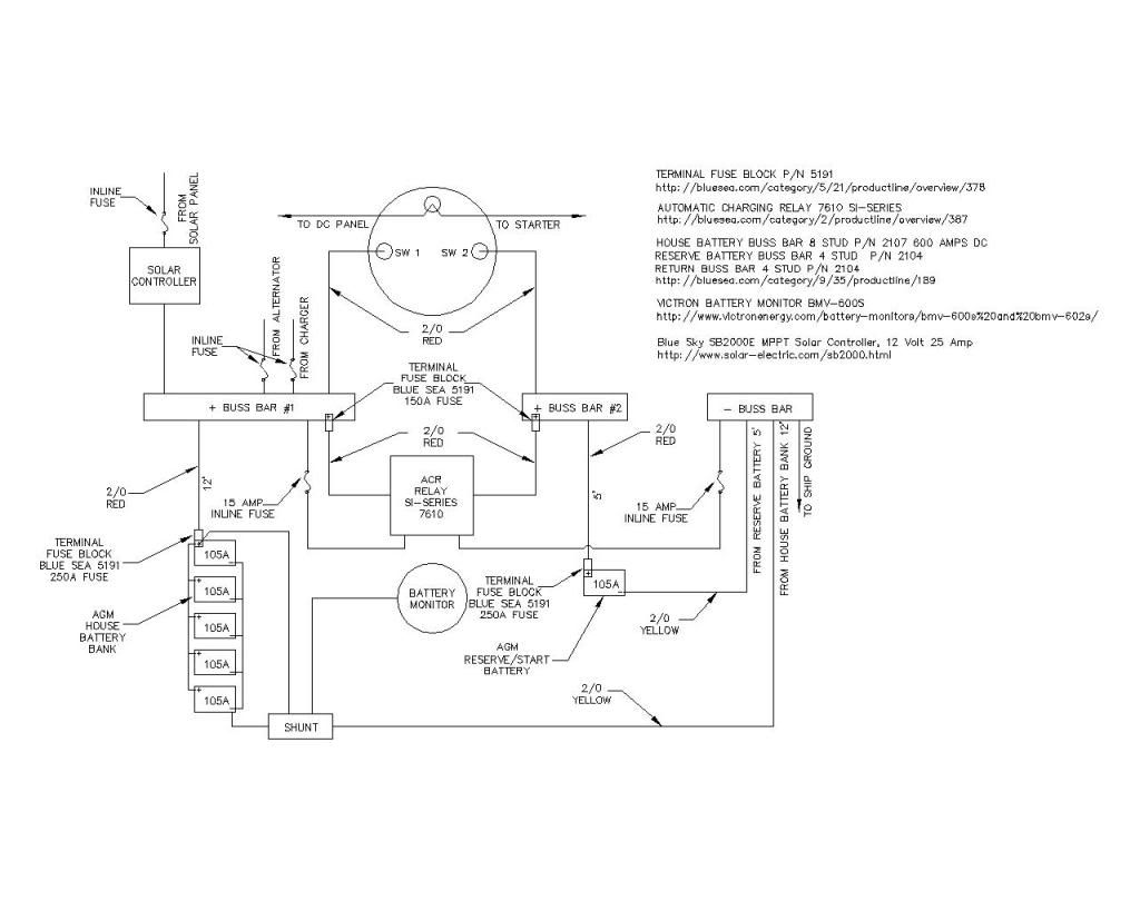
I am new to this site and have been following this and other threads for some time. I am the new owner of a 1984 Catalina 27 with a Universal M-18 inboard diesel. I find myself in the same situation as many used boat owners. The marine insurance survey I purchased identified several electrical and battery issues, so I want to straighten these out before I hit Chesapeake Bay this spring. I plan to use a similar design as that provided by CTJ1950. Thank you for providing this, and thanks to all the folks that provided great comments in this thread (Stu Jackson, Maine Sail, mitiempo and all others).

I have already been crawling around my boat and have identified that the output of the alternator goes to the dreaded orange wire #4 in the wiring harness. I will make the necessary modification to that wire and take the alternator output off the ammeter and 1/2/Both/Off switch and land it to a new positive busbar from the house bank. My existing batteries are apparently pretty much gone too, so I am considering two flooded golf cart batteries wired in series for 225AH 12v on the house bank. I will purchase a single 12 flooded battery for the reserve. My boat currently has a 1.5 amp float charger. I believe that is inadequate to achieving good battery life, so I plan to replace that with an IOTA DLS-30 with the integral smart charger. Other than that I will pretty use the plan provided by CTJ1950.

That said, I do have several questions with the design. If someone could provide answers I'd be very thankful.

1) Battery disconnect switches - on/off. I was told by the Marine Surveyor I hired that these were required by code (ABYC?). They are not in the design. I plan on using Blue Sea systems on/off micro switch on each bank. Comments?

2) Busbar sizing - The subject design contains 600 amp continuous rating busbar. I am thinking that this is overkill for my Universal M-18 diesel, original alternator (51 amp?), SI-ACR and IOTA 30 amp battery charger. I have viewed the starting current videos provided by Maine Sail on a separate thread (thank you), and have come to the conclusion that perhaps using 250 amp busbar might be better in my application? Comments?

3) Fusing the wiring to the 1/2/both/off switch. I notice that in the provided diagram these wires are not fused. Do they require fuses?

Well, thats alot of questions, and I may have more. Your answers and thoughts should provide me with what I need to get started. Thanks to all in advance for your help.

Sincerely,

Boomer
Catalina 27 #5688
 
#16 · (Edited)
Boomer,

#1 A battery disconnect switch is simply a battery switch. Each bank needs to be capable of being turned off or isolated. Any 1/2/BOTH, ON/OFF or DCP battery switch will meet this requirement.

It is not clear whether you want to use your existing 1/2/BOTH or two ON/OFF switches?

#2 The Blue Sea 250A bus bar is fine

#3 If you want to follow ABYC standards the house bank needs fusing within 7" of the positive battery post. However, on a small sailboat AUX engien where fusing is simple and inexpensive, it is always a GOOD IDEA to also fuse the start bank. A 250A fuse or larger, provided your wire can handle it should be used if starting off that bank. Any time your wire changes size you need to address fusing again and make sure your OCP is not too large for the wire.

If you own a Universal M-18 be sure to check that you have the upgraded alternator bracket.

Universal M-18 & M-25 Alternator Bracket Upgrade
 
#18 · (Edited)
It's spelt "busbar" btw. From the latin, Omnibus, or "for all"

Boomer, I've just been upgraded the cabling on my Universal 5424, because it was turning over a little slowly.

I added the Blue Sea systems fuse holders that go on the battery terminals. I also upgraded the cables to 2/0, from genuinedealz.com. They make very nice cables at a great price.

I changed the 1-2-both-off switch to the Blue Sea systems one, the m-series rated to 300A. After going to a lot of trouble making a wooden plate with a hole in to cover the hole left by my existing switch, I found that the larger e-series would have fitted better. Never mind. The m-series comes with a nice built-in cover for the rear connections, which is good for safety.

I think the supply wires to your shunt and AH meter should be fused according to their gauges, near to the battery.
 
#19 · (Edited)
It's spelt "busbar" btw. From the latin, Omnibus, or "for all"
Mark,

Can you please let Merriam-Webster know this...;)
Bus bar - Definition and More from the Free Merriam-Webster Dictionary

We may also want to let Tyco/AMP/TE Connectivity know they spell it wrong..
http://www.te.com/catalog/connector/bus-bar/menu/en/17694

BEP Marine Needs to know this too..
http://www.bepmarine.com/home-mainmenu-8/productcategory-263/bus-bars-covers

Newmar should know too...
http://www.newmarpower.com/Terminal_Strips_Bus_Bars/Terminal_Strips_Bus_Bars.html

Even large electrical supply companies like Hubbell/Burndy spell it wrong:
http://www.hubbell.com/hq/PDF/burndy-datacenter-brochure.pdf

We can't leave out standards organizations like ASTM:
http://www.astm.org/Standards/B187.htm

Even TnB (Thomas & Betts) spell it wrong:
http://www.tnb.com/ps/endeca/index.cgi?a=nav&N=4294951481

Wow Belden spells it wrong too:
http://www.belden.com/products/cata...stercatalog/hookupleadwire/upload/Bus-Bar-Antenna-Aluminum-Ground-68k-03-27.pdf

Littelfuse too:
http://www.littelfuse.com/industries/solar/bus-bar.aspx

Paneltronics:
http://www.paneltronics.com/Electrical_Components.asp?op=Terminal-Blocks-and-Bus-Bars

Multiple sources note that it can be spelled either way and I suspect folks will know exactly what you mean when spelled (spelt) busbar or bus bar........
 
#20 ·
My post could be confusing. I agree it's spelt "busbar" or "bus bar". However, it is not spelt bussbar, or buss bar. That was intended to be my point.

If we are to follow the normal conventions, it should ideally be "bus-bar".

I think I'm going to start calling it the omnibus-bar.
 
#21 ·
I understand what it means no matter how it is spelled. I kind of like omnibus-bar..;)

It's kind of like the folks who insist it is a cutless bearing yet the word Cutless® is a registered trademark of Duramax Marine® LLC.. The words stave, sleeve or cutlass bearing are the accepted generic terms.

Most people would have no clue what you are talking about if you used the word stave bearing but if you say cutlass everyone knows.
 
#27 ·
Hi Maine Sail,

Thank you for the input. On my question #1 related to battery disconnect switches, I was assuming (I know.. I know...) that I would need to add a new disconnect (on/off) switch for each bank. The marine surveyor wrote "A single wire should lead from each battery bank to disconnect switch. That wire should be fused with slow blow fuse rated for wire gauge. All other wires should come off of buss bar aft of disconnect switch." I assumed he meant a separate disconnect switch for each bank close to the batteries before the busbars, and not the 1/2/Both/Off switch which will disconnect the batteries from the DC distribution panel but not isolate the batteries from the positive busbars and loads / chargers shown in ctj1950's wiring diagram. Am I misreading this requirement? I can add the on/off switches if needed.

Thanks too for the information about the Universal M-18 Alternator bracket. More work to do. :)

And to ctj1950... thanks for the diagram.. and fyi... my boat is on the hard in Mayo, MD... moving to Deale, MD in the spring. That close to you???

Thanks again.

Boomer
Catalina 27 #5688

PS... I didn't mean to start a grammar war!
 
#28 ·
You do not need additional ON/OFF switches on top of the 1/2/BOTH.... The only devices before the battery switch are items like the alternator, which should ideally be fused and ideally have it's own "service disconnect", perhaps a VHF, your bilge pump and any ACR or Echo type charger. On bigger boats and inverter may tie in before the batt switch, but should have its own ON/OFF and a windlass or thruster may as well..... Anything tied in before the batts switch should have sufficient over current protection.

Battery fuses should be ANL, MRBF or Class T....
 
#29 ·
... or disk drive vs disc drive (which was IBM's term)

Sent from my VS930 4G using Forum Fiend v1.1.3.
 
#30 ·
Hey cjt1950... Thanks for the crimper usage offer. I cannot respond via private message yet... I've not made enough posts yet apparently. As FYI... my boat will be at the same location in April. So will have to look you up sometime.

Take care,

Boomer